
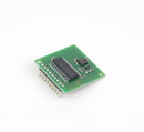
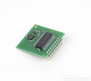
CMPS03 - Magnetic Compass
Devantech
This compass module has been specifically designed for use in robots as an aid to navigation. The aim was to produce a unique number to represent the direction the robot is facing.
The compass uses the Philips KMZ51 magnetic field sensor, which is sensitive enough to detect the Earths magnetic field. The output from two of them mounted at right angles to each other is used to compute the direction of the horizontal component of the Earths magnetic field.
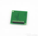
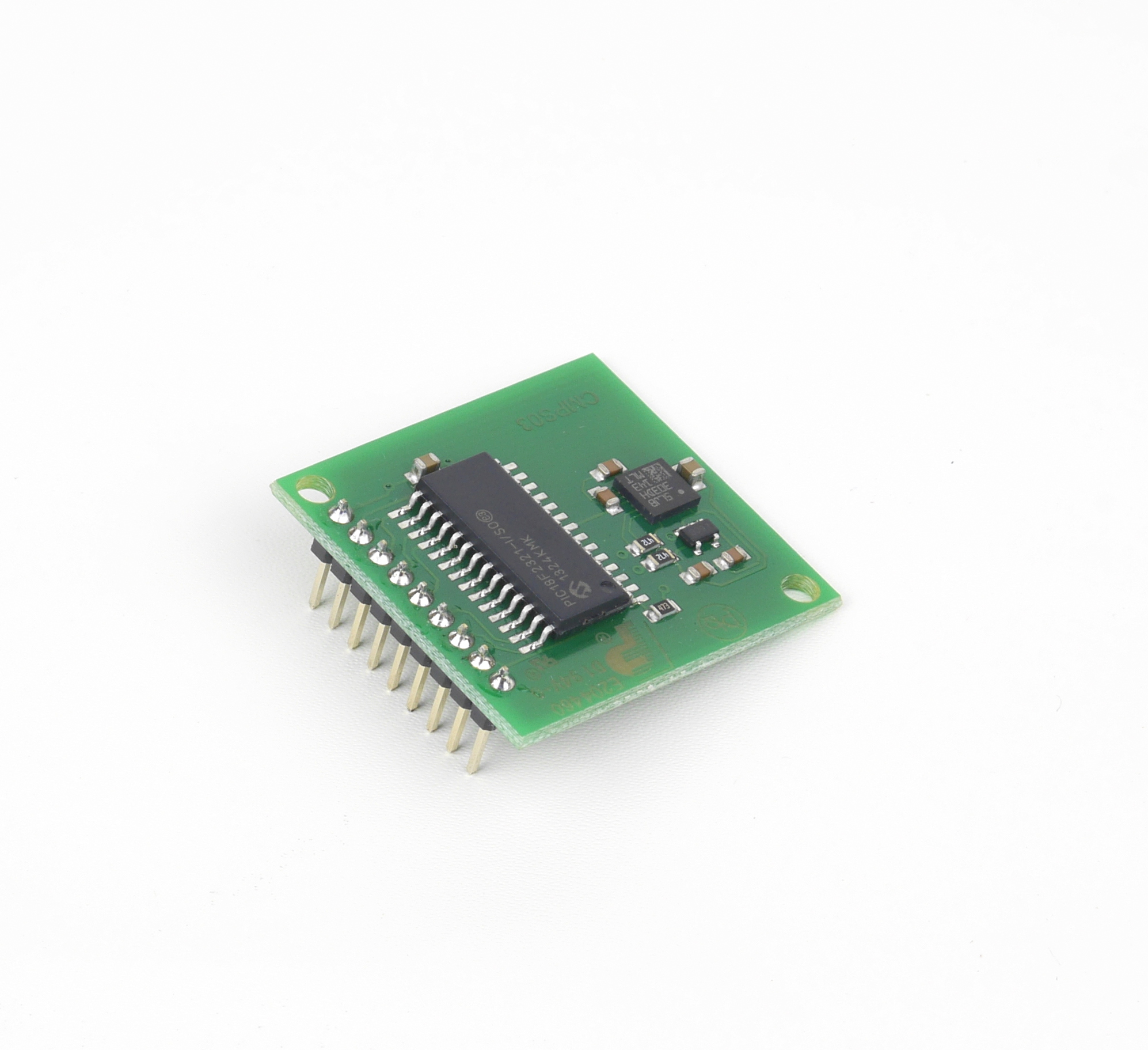
Connections
There are two ways of getting the bearing from the module. A PWM signal is available on pin 4, or an I2C interface is provided on pins 2,3.
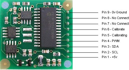
Pin 1, +5v. The compass module requires a 5v power supply at a nominal 25mA.
Pins 2,3 are the I2C interface and can be used to get a direct readout of the bearing. If the I2C interface is not used then these pins should be pulled high (to +5v) via a couple of resistors. Around 47k is ok, the values are not at all critical.
Pin 4. The PWM signal is a pulse width modulated signal with the positive width of the pulse representing the angle. The pulse width varies from 1mS (0° ) to 36.99mS (359.9° ) – in other words 100uS/° with a +1mS offset. The signal goes low for 65mS between pulses, so the cycle time is 65mS + the pulse width - ie. 66ms-102ms. The pulse is generated by a 16 bit timer in the processor giving a 1uS resolution, however I would not recommend measuring this to anything better than 0.1° (10uS). Make sure you connect the I2C pins, SCL and SDA, to the 5v supply if you are using the PWM, as there are no pull-up resistors on these pins.
Pin 5 is used to indicate calibration is in progress (active low). You can connect an LED from this pin to +5v via a 390 ohm resistor if you wish.
Pin 6 is one of two ways to calibrate the compass, the other is writing 255 (0xFF) to the command register. Full calibration instructions are further down this page. The calibrate input has an on-board pull-up resistor and can be left unconnected after calibration.
Pins 7 and 8 are currently unused. They have on-board pull-up resistors and should be left unconnected.
Pin 9 is the 0v power supply.
PCB Drilling Plan
The following diagram shows the CMPS03 PCB mounting hole positions.
Manufacturer's data
Technical Specification - link to the manufacturer
CMPS03 FAQ - link to the manufacturer
Product information for: CMPS03 - Magnetic Compass
Publishing date (date of last technical specification): 2007-03-01
Shipping weight: 200 g
Manufacturer: Devantech
Brand: ROBOT ELECTRONICS
Article number: DEV-CMPS03
Manufacturer's part number: CMPS03
Contact us
Obsolete item
This item is not available any more. Some components might no longer be manufactured or there is an improved successor model.
Share
About ROBOT ELECTRONICS
ROBOT ELECTRONICS is a brand by English manufacturer Devantech Ltd., based in Norfolk. Product range comprises sensors, in particular ultrasonic or compass, servocontrollers as well as small robot drive systems or relay modules with various interfaces. Sensors are produced in England and are of consistently high quality.
More from ROBOT ELECTRONICS